
Implant Collar Surface Properties and Marginal Bone Loss
Implant Collar Surface Properties and Marginal Bone Loss
Osseointegration is an essential requirement for allowing the survival of dental implants in the jaw bone. Factors such as unfavorable stress distribution, surgical trauma, implant-abutment microgap, and bacterial infiltration can detrimentally affect osseointegration [1, 2] and accelerate bone loss.
According to the literature, most if not all implants will cause to some extent marginal bone Loss (MBL) during their lifetime [3]. Efforts have been made to reduce MBL and to avoid its associated complications. Studies have shown that several factors such as implant surface quality [4] implant neck macro and micro design [5] and crestal implant position (6) play particularly crucial roles in osseointegration.
Surface area may be increased using proper modification techniques, either by addition or subtraction procedures. Surface treatments can also be classified as mechanical, chemical, and physical methods. Surface treatments of dental implants are used to modify their topography and energy, resulting in improved wettability, increased cell proliferation and growth, and in accelerated osseointegration [7].
Alpha-Bio Tec.’s Sand blast Large grit Acid etch (SLA) implant surface is created through two processes: a sand- blasting process for a macro surface of 20-40 microns and a double thermal acid etching process to create micro pitting between 1-5 microns.
There is no consensus in the literature concerning the effectiveness of various implant surface neck configurations and their effect on MBL. The aim of this review is to compare the influence of machined and SLA neck surface on MBL levels during the implant’s existence in the bone.
Limited available data suggests that smooth surfaces (machined) are less involved in peri-implantitis than rough surface implants [8]. This observation is potentially supported by reduced plaque accumulation around the implants with a reduced roughness (9). However, further research has shown that surface porosity impacts on osseointegration by allowing direct 3D ingrowth of osteogenic cells into the implant, thereby strengthening the bone-implant interface [10].
Acid etched surfaces enhance the osseointegration by increasing cell adhesion and bone formation [7]. This hypothesis was demonstrated in in-vitro studies showing osteoblasts growing on SLA surfaces. These osteoblasts are highly differentiated bone cells, suggesting that this pitted surface enhances bone cell-implant integration [11].
Preclinical and clinical studies suggest that there are several factors that individually and cumulatively influence MBL levels. Therefore, studies have been conducted that typically combine two or more crestal neck features to evaluate the best combination of features to reduce MBL.
Certain studies did not confirm that a rough surface combined with a microthreaded neck has a positive effect on the MBL [12]. However, the majority of the reviewed works show a different picture.
Bratu et al. (2009) compared marginal bone loss between implants with SLA treatment and coronal microthreads and polished neck implants. The results showed statistically significant lower MBL in combined SLA/microthread implants.
Another study showed a greater bone loss in implants with a machined surface neck design without microthreads in the first year [9].
The long term study of Piao et al. showed that a rough surface with micro-threads at the coronal part of implant maintained the marginal bone level against functional loading better than implants without these two features after a follow up of one year [13] and confirmed these results after a three year follow up [14].
Additionally, Shin et al. (2006) have shown in their work that a rough surface and micro-threads at the implant neck not only reduce crestal bone loss but also help with early biomechanical adaptation against loading in comparison to the machined neck design. They concluded that a rough surface with microthreads at the implant neck is the most effective design in maintaining the marginal bone level against functional loading [15].
In another study, a correlation between collar design, implant placement and MBL in a canine model was evaluated. The study data showed that the placement of a polished area subcrestally facilitates higher rates of early MBL [6], whereas a rough implant surface placed at the bone level reduces the amount of this bone loss [16, 17].
Conclusions
Based on the reviewed literature, we can conclude that marginal bone changes around rough-surfaced micro-threaded neck implants are significantly lower than in polished or rough surfaced implants.
All Alpha-Bio Tec.'s implants have rough SLA surface and microgrooves which contribute to osseointegration and reduce MBL.
References
1. Baffone GM, Botticelli D, Pereira FP, Favero G, Schweikert M, Lang NP., Influence of buccal bony crest width on marginal dimensions of peri-implant hard and soft tissues after implant installation. An experimental study in dogs. Clin Oral Implants Res. 2013 Mar;24(3):250-4.
2. Bengazi F, Lang NP, Caroprese M, Urbizo Velez J, Favero V, Botticelli D. Dimensional changes in soft tissues around dental implants following free gingival grafting: an experimental study in dogs. Clin Oral Implants Res. 2015 Feb;26 (2):176-82.
3. Albrektsson T, Zarb G, Worthington P, Eriksson AR. The long-term efficacy of currently used dental implants: a review and proposed criteria of success. Int J Oral Maxillofac Implants 1986;1:11–25.
4. Lai H-C, Zhuang L-E, Zhang Z-Y, Wieland M, Liu X. Bone apposition around two different sandblasted, large-grit and acid-etched implant surfaces at sites with coronal circumferential defects: an experimental study in dogs. Clin. Oral Impl. Res. 20, 2009; 247–253.
5. Penarrocha, M., Palomar, M., Sanchis, J.M., Guarinos, J. & Balaguer, J. (2004) Radiologic study of marginal bone loss around 108 dental implants and its relationship to smoking, implant location, and morphology. International Journal of Oral & Maxillofacial Implants 19: 861–867.
6. Alomrani AN, Hermann JS, Jones AA, Buser D, Schoolfield J, Cochran DL. The effect of a machined collar on coronal hard tissue around titanium implants: a radiographic study in the canine mandible. Int J Oral Maxillofac Implants. 2005 Sep-Oct;20(5):677-86.
7. Jemat A., Ghazali M. J., Razali M., and Otsuka Y.; Surface Modifications and Their Effects on Titanium Dental Implants Biomed Res Int. 2015:791725
8. Renvert S, Polyzois I, Claffey N. How do implant surface characteristics influence peri-implant disease? J Clin Periodontol. 2011 Mar; 38 Suppl 11:214-22.
9. Pen ̃arrocha-Diago MA, Flichy-Ferna ́ndez AJ, Alonso- Gonza ́lez R, Pen ̃arrocha-Oltra D, Balaguer-Martı ́nez J, Pen ̃arrocha-Diago M. Influence of implant neck design and implant–abutment connection type on peri-implant health. Radiological study. Clin. Oral Impl. Res. 24, 2013, 1192–1200
10. Bill G. X. Zhang, Damian E. Myers, Gordon G. Wallace, Milan Brandt and Peter F. M. Choong Bioactive Coatings for Orthopaedic Implants—Recent Trends in Development of Implant Coatings Int. J. Mol. Sci. 2014, 15, 11878- 11921
11. Kieswetter K, Schwartz Z, Hummert TW, Cochran DL, Simpson J, Dean DD, Boyan BD. Surface roughness modulates the local production of growth factors and cytokines by osteoblast-like MG-63 cells. J Biomed Mater Res 32, 1996, 55–63
12. Bassetti R., Kaufmann R., Ebinger A, Mericske-Stern R., Enkling N, Is a grooved collar implant design superior to a machined design regarding bone level alteration? An observational pilot study. Quintessence international March 2014
13. Piao, C.M., Lee, J.E., Koak, J.Y., Kim, S.K., Rhyu, I.C., Han, C.H., Herr, Y., Heo, S.J. (2009). Marginal bone loss around three different implant systems: radiographic evaluation after 1 year. Journal of Oral Rehabilitation 36: 748–54.
14. Lee SY, Piao CM, Koak JY, Kim SK, Kim YS, Ku Y, Rhyu IC, Han CH, Heo SJ. A 3-year prospective radiographic evaluation of marginal bone level around different implant systems. J Oral Rehabil. 2010 Jul;37(7):538-44.
15. Shin, Y.K., Han, C.H., Heo, S.J., Kim, S. & Chun, H.J. (2006) Radiographic evaluation of marginal bone level around implants with different neck designs after 1 year. International Journal of Oral & Maxillofacial Implants 21: 789–794.
16. Hartman GA, Cochran DL. Initial implant position determines the magnitude of crestal bone remodeling. J Periodontol. 2004 Apr;75(4):572-7.
17. Hanggi, M.P., Hanggi, D.C., Schoolfield, J.D,. Meyer, J., Cochran, D.L. & Hermann, J.S.
Crestal bone changes around titanium implants. Part i: a retrospective radiographic evaluation in humans comparing two non-submerged implant designs with different machined collar lengths. Journal of Periodontology 2005; 76: 791–802.
Czystość implantu Alpha-Bio Tec Badanie przeprowadzone przez Dział Jakości i Kontroli Alpha-Bio Tec (QA).
Executive Summary
Background
The following document describes routine Quality Assurance (QA) and Quality Control (QC) procedures performed by the Alpha-Bio Tec. QA department on implants. The examples and details are provided here for the SPI implant. Alpha-Bio Tec. provides this document to academic and professional communities, in order to share information about production and QA as well as demonstrating the Company’s high production standards.
Alpha-Bio Tec
Alpha-Bio Tec. specializes in the development and production of advanced dental solutions, focusing on implants and prosthetics. Alpha-Bio Tec. developed the SPI, the original spiral implant.
Since it was established in 1988, Alpha-Bio Tec. has spearheaded dental implantology innovation, supporting its products through rigorous manufacturing and quality assurance standards. Alpha-Bio Tec. has a research and development
team comprised of top-tier dentistry experts.
Alpha-Bio Tec Implant Surface
The Alpha-Bio Tec. Implant Surface is created through a sand-blasting process to form a macro surface of 20-40 microns and a double thermal acid etching process to create micro pitting between 1 to 5 microns. The advantages of this implant surface - confirmed by retrospective clinical data showing an overall clinical success rate of 98.3% and a 99.6% when using the immediate loading procedure - are to increase early bone-to-implant contact (BIC); increase stability; shorten healing period; and produce higher performance predictability.
Quality Assurance and Quality Control
Alpha-Bio Tec. products are compliant with the world’s leading quality systems and standards: ISO 13485:2003 including the Canadian Medical Devices Conformity Assessment System and Council Directive 93/42/EEC.
In addition, Alpha-Bio Tec. has gained FDA approval for immediate loading of single tooth for SPI and ARRP implants. Its medical devices are CE-approved and cleared for marketing in the USA.
All this allows clinicians using Alpha-Bio Tec. products to achieve proven, long term success, supported by a Lifetime Warranty for its wide range of implants.
SEM and XPS analyses
Alpha-Bio Tec. implants are routinely examined by third party, certified laboratories as part of Alpha-Bio Tec. Standard Operating Procedures (SOPs). The following report, which is an example of such examination, describes Alpha-Bio Tec. implants from batch 14058302 that were analyzed in the Tel Aviv University, WOLFSON APPLIED MATERIALS RESEARCH CENTRE, by two different experts: one for the scanning electron microscopy (SEM) and the other for x-ray photoelectron spectroscopy (XPS) analysis. For explanation of technical terms please refer to the dictionary in Annex 1.
Conclusions
This report demonstrates the excellent degree Alpha-Bio Tec. implants surface cleanliness and microstructure of Alpha-Bio Tec. implants subject as shown by SEM and XPS examinations.
Alpha-Bio Tec. implants and thus their surface were proven to provide predictable clinical outcomes as shown in retrospective and prospective clinical studies as further detailed below.
Materials and Methods
§ SEM
Scanning electron microscopy (SEM) enables the topical evaluation of the implant surfaces. Backscattered electron imaging (BSE) allows drawing conclusions about the chemical nature (density) and allocation of different contaminations in the sample material. Secondary electron imaging (SE) facilitates drawing conclusions about the surface topography.
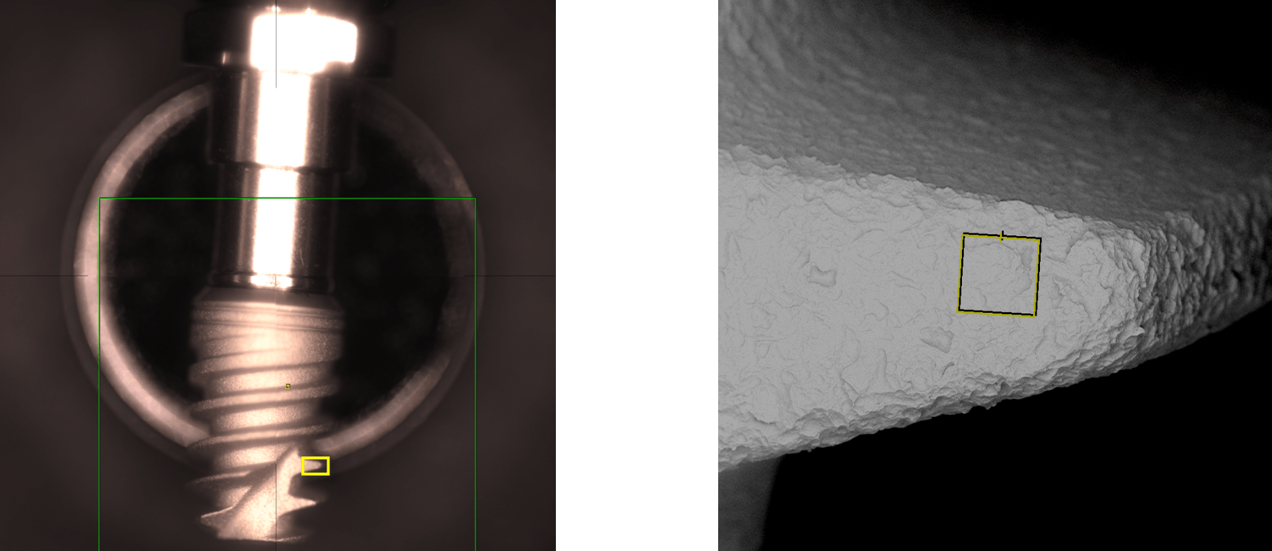
Implant surface was observed by §SEM with §§BSE and §§§SE field. SEM images were taken from various parts of the implant, area 1 from the coronal part, area 2 from the apical part of the implant, Figure 1 and 2 correspondingly.
§§§§ XPS
X-ray photoelectron spectroscopy (XPS) (see Appendix A) measurements were performed in UHV (2.5x10 -10 Torr base pressure) using 5600 Multi-Technique System (PHI, USA). The samples were irradiated with an Al K monochromated source (1486.6 eV) and the outcome electrons were analyzed by a spherical capacitor analyzer using the slit aperture of 0.8 mm. All the measurements were done at a take-off angle (the angle between the sample surface and the analyzer) of 45o. The samples were slightly charged during measurements and this charging was compensated with the charge neutralizer and mathematically (C1s at 285 eV was taken as an energy reference for all the peaks, mathematical shifts are given on the presented spectra*).
Goal
Demonstration of compositional and chemical bonding analysis of Alpha-Bio Tec. dental implant in predefined different points.
Results
a.§SEM Examinations
Implant surface was observed by §SEM with §§BSE field. SEM images were taken from various parts of the implant, area 1 from the coronal part, area 2 from the apical part of the implant, Figures 1 and 2 respectively.
b.§§§§XPS Examination
The sample was analyzed in two different points as shown on the presented image in Figure 5; point 1 from flat area in the coronal part and point 2 from the thread area (mid of threaded part).
The XPS spectra obtained from the analyzed areas are shown in Figure 6 and the quantitative atomic concentration results are summarized in Table 1.
Table 1- XPS Atomic Concentration
Summary and Conclusions
This report demonstrates the excellent surface cleanliness and structure of Alpha-Bio Tec. implants through SEM and XPS examinations.
The atomiccomposition that is demonstrated in this report, proves the excellent purity of the ABT implant. This Atomic composition combined with implant surface morphology is reported in many independent, objective scientific reports as facilitating successful osseointegration1-6.
Despite the lack of broad scientific consensus regarding what is the optimal composition of outer implant surface to ensure osseointegration, Alpha-Bio Tec. implants surface have proven they provide predictable clinical outcomes in retrospective and prospective clinical studies. The results also support the low failure rate of ABT implants that are returned from users (the company provides life time warranty and “no questions asked” return policy that assure good visibility of actual implants failure rates).
As part of Alpha-Bio Tec’s standard operating procedures (SOPs), its implants are subject to the strict analytical evaluations concerning the implants surface cleanliness and structure. These evaluations, which are performed internally as well as by third party academic institutions, enable Alpha-Bio Tec. to verify the high quality of its production process.
References
1. Sawase T, Hai K, Yoshida K, Baba K, Hatada R, Atsuta M.
Spectroscopic studies of three osseointegrated implants. J Dent. 1998 Mar;26(2):119-24.
2. Jarmar T, Palmquist A, Brånemark R, Hermansson L, Engqvist H, Thomsen P.
Characterization of the surface properties of commercially available dental implants using scanning electron microscopy, focused ion beam, and high-resolution transmission electron microscopy. Clin Implant Dent Relat Res. 2008 Mar;10(1):11-22
3. Sul YT, Johansson CB, Petronis S, Krozer A, Jeong Y, Wennerberg A, Albrektsson T
Characteristics of the surface oxides on turned and electrochemically oxidized pure titanium implants up to dielectric breakdown: the oxide thickness, micropore configurations, surface roughness, crystal structure and chemical composition. Biomaterials. 2002 Jan;23(2):491-501
4. Sul YT, Johansson C, Wennerberg A, Cho LR, Chang BS, Albrektsson T.
Optimum surface properties of oxidized implants for reinforcement of osseointegration: surface chemistry, oxide
thickness, porosity, roughness, and crystal structure. Int J Oral Maxillofac Implants. 2005 May-Jun;20(3):349-59.
5. Smith DC.
Dental implants: materials and design considerations. Int J Prosthodont. 1993 Mar-Apr;6(2):106-17.
6. Huré G1, Donath K, Lesourd M, Chappard D, Baslé MF.
Does titanium surface treatment influence the bone-implant interface? SEM and histomorphometry in a 6-month sheep study. Int J Oral Maxillofac Implants. 1996 Jul-Aug; 11(4):506-11.
Appendix 1 - Dictionary
§ SEM - scanning electron microscope
A scanning electron microscope (SEM) is a type of electron microscope that produces images of a sample by scanning it with a focused beam of electrons. The electrons interact with atoms in the sample, producing various detectable signals that contain information about the sample's surface topography and composition.
§§BSE
Backscattered electrons (BSE) consist of high-energy electrons originating in the electron beam that are reflected, or back-scattered, out of an examined specimen in SEM device.
§§§SE
Secondary electrons (SE) are the emitted lower-energy electrons that result from inelastic scattering. The energy of secondary electrons is typically 50 eV or less.
§§§§ XPS- X-ray Photoelectron Spectroscopy
X-ray photoelectron spectroscopy (XPS) is a surface-sensitive quantitative spectroscopic technique that measures the elemental composition at the parts per thousand range, empirical formula, chemical state and electronic state of the elements that exist within a material. XPS spectra are obtained by irradiating a material with a beam of x-rays while simultaneously measuring the kinetic energy and number of electrons that escape from the top 0-10 nm of the material being analyzed. XPS requires high vacuum (P ~ 10−8 millibar) or ultra-high vacuum (UHV; P < 10−9 millibar) conditions, although a current area of development is ambient-pressure XPS, in which samples are analyzed at pressures of a few tens of millibar
Appendix 2: Performed Measurements
* Survey: spectrum in a wide energy range (0 - 1400 eV). It gives an estimate of the elements present on the sample surface and is taken at a low resolution.
** Utility Multiplex: spectra taken for different peaks in a low energy range window at an Intermediate (Utility) Resolution. It is taken for all the elements present for the atomic concentration (AC%) calculation. An AC table is given as an output of these measurements. AC calculation accuracy:
+_ 2% for AC around 50%
+_ 5% - 20%
+_10% - 5%
+_20% - 1%
*** High Resolution Multiplex: spectra taken for different peaks in a low energy range window at a High Resolution (PE = 11.75 eV, 0.05 eV/step). These measurements allow precise energy position and peak shape determination, necessary for bond bonding analysis.
Badanie powierzchni implantu SPI metodą SEM oraz EDX
Quantitative and qualitative element-analysis of implant-surfaces by SEM and EDX
PRELIMINARY STUDY REPORT
1 Background and Aim
Implant surfaces are modified by microstructures and surface extension to improve osseointegration. Numerous studies showed an increased adhesion and osteoblastic matrix-production on retentive titanium surfaces.
In 2008 the University of Cologne, Germany and the BDIZ EDI (European Association of Dental Implantology) with its Quality and Research (Q&R) Committee (www.bdizedi.org) performed a scanning electron microscopic study and analyzed the surfaces of 23 enossal titanium implants of several manufacturers at the Interdisciplinary Policlinic for Oral Surgery and Implantology, Department for Craniomaxillofacial and Plastic Surgery, University Cologne1. The tested implants showed isolated and/or extensive deposits. Depending on manufacturing process, accumulations of organic material (carbon) or inorganic material like aluminum, silicon, phosphor, sulfur, chlorine, potassium and calcium were found.
In 2011-2012 we performed the same protocol on 57 dental implants from different manufacturers. However, the manufacturing of implants requires an adequate system of quality controls. Although some manufacturers have made substantial improvements since our first survey in 2008, the study in 2011-2012 again singled out a few implants with larger areas of surface blasting residue and selective organic impurities2.
The BDIZ EDI3, representing more than 5,500 active implantologists in Europe, was asked in its general meeting to continue these analyses periodically and to publish the results in the European EDI Journal.
While using the same material an methods regarding the technical setup this study allows comparisons to the results of previous studies.
As a continuance of the two studies cited above the aim of this study is to verify improvements of manufacturing and quality management as well as to demonstrate the high quality level of the participating manufacturers and implant companies.
2 Material and Method / Study Protocol
2.1 Scientific Workstation and Test Procedure
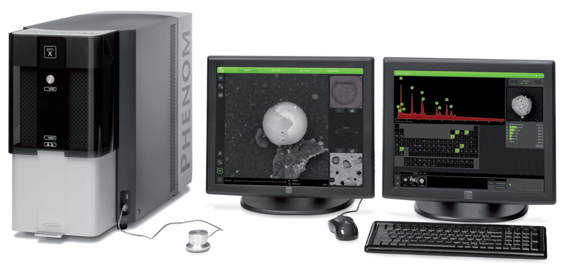
The scientific workstation is a Phenom proX Scanning Electron Microscope, equipped with a high-sensitivity backscattered electron detector that allows compo- sitional and topographical imaging modes. EDX analyses are performed with a thermoelectrically cooled Silicon Drift Detector (SDD).
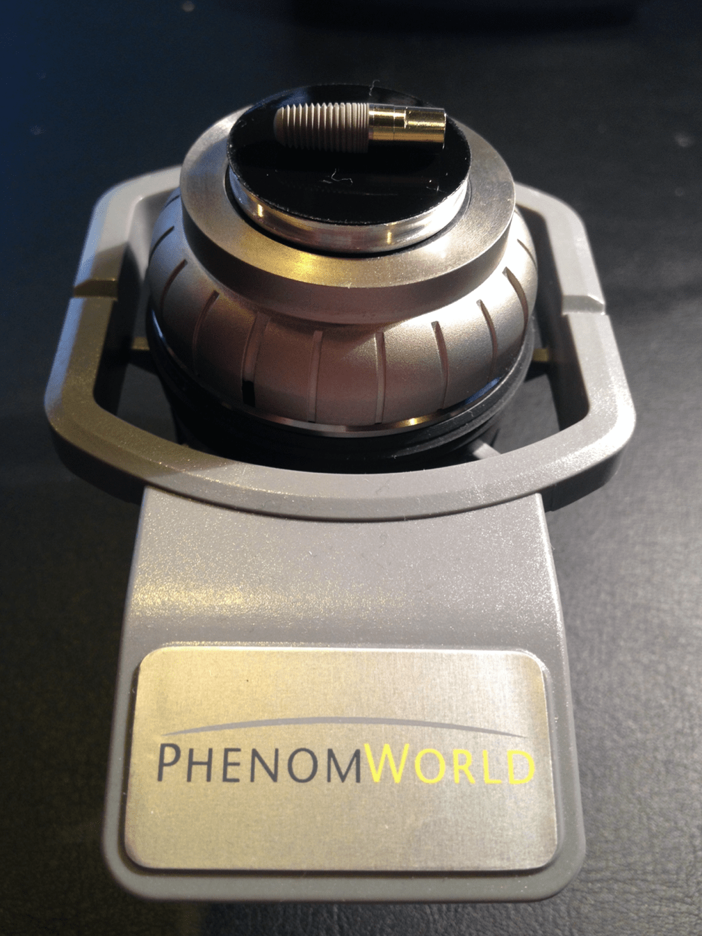
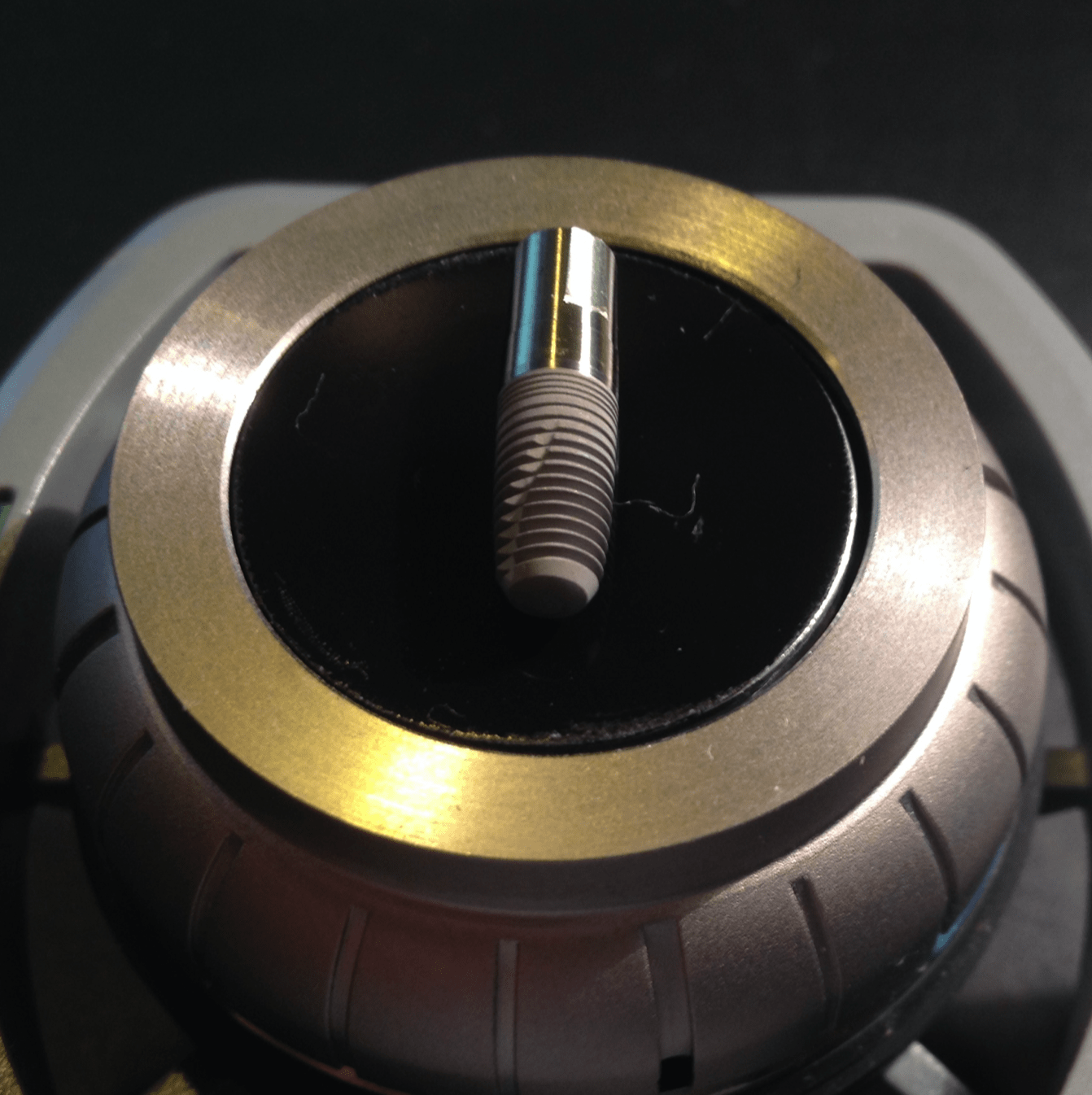
Without touching the surface, each implant will be taken out of the package with sterile forceps and will be fixed on the sample holders. After the vacuum is generated in the electron microscope imaging and EDX-analyses will be completed.
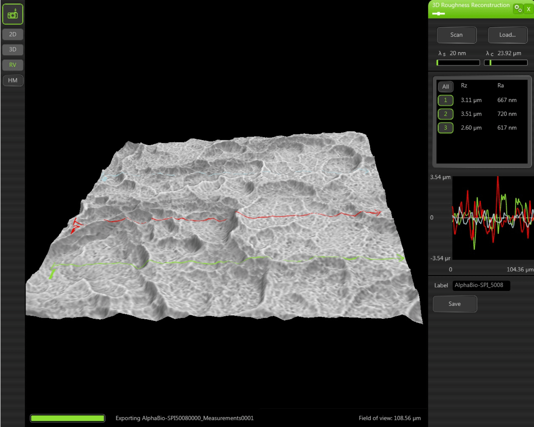
2.2 3D Roughness Reconstruction
With a specific 3D roughness reconstruction application, based on a „shape from shading” technology, the SEM system used in this study is able to generate three- dimensional images and submicrometer roughness measurements.
3D imaging helps to interpret sample characteristics and makes images under- standable. In addition the system is able to measure the average roughness (Ra) and the roughness height (Rz). Due to shape-from-shading technology Ra and Rz data in this study are to be generally understood merely as approximate values.
2.3 SEM-Examination of Implant Surface
Scanning electron microscopy (SEM) enables the topical evaluation of the implant surface. In particular at low voltages and small working distances, images with high contrast can be obtained. The high-sensitivity backscattered electron detector is generating images in compositional and topographical modes to a magnification of 20.000x.
Besides information about morphology and surface topography, the BSE detector allows to draw conclusions about the chemical nature and allocation of different remnants or contaminations on the sample material.
2.4 Qualitative and Quantitative Analysis of Implant Surfaces(EDX)
Energy Dispersive X-ray Spectroscopy (EDX) analyzes X-rays generated by the electrons of the electron beam (CeB6 electron source) while they are interacting with the sample. Each element emits specific X-ray peaks. The element identification software allows to identify even hidden elements within the sample via the spot mode analysis. All results are verified using iterative peak stripping deconvolution. An area-analysis and one or more spot analyses are performed for each tested implant (analysis of spots and areas by EDX). An area-analysis covers the entire implant area in the focus of the microscope. For a spot analysis, the electron beam is focused on a specific area to get information about selective accumulations on the implant surface.
If necessary, elemental mapping reveals the distribution of elements within the sample. Selected elements can be mapped. Compiling these elements with the backscattered image gives a clear insight into the distribution of elements within the sample. Line scan allows analysis to be performed over a selected line. A line profile of every selected element is displayed on the screen.
5
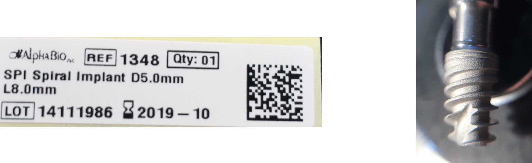
3 Alpha-Bio Tec - SPI Spiral Implant LOT 14111986
3.1 3D Roughness Reconstruction
3.2 Surface-Topography - Material Contrast Images (Thread)
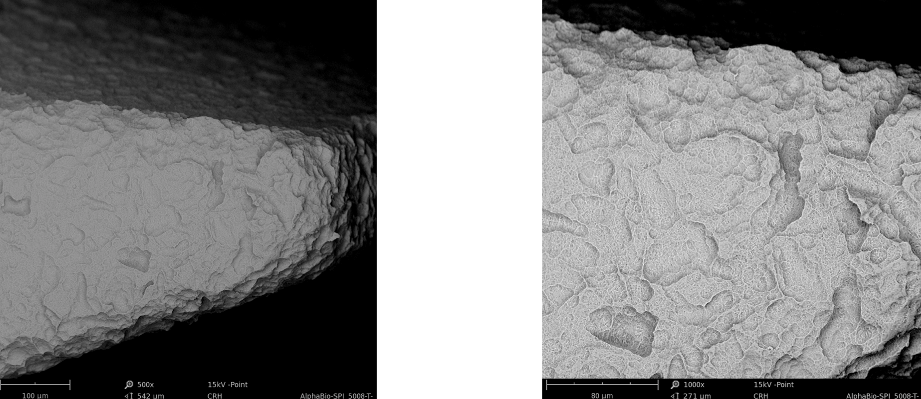
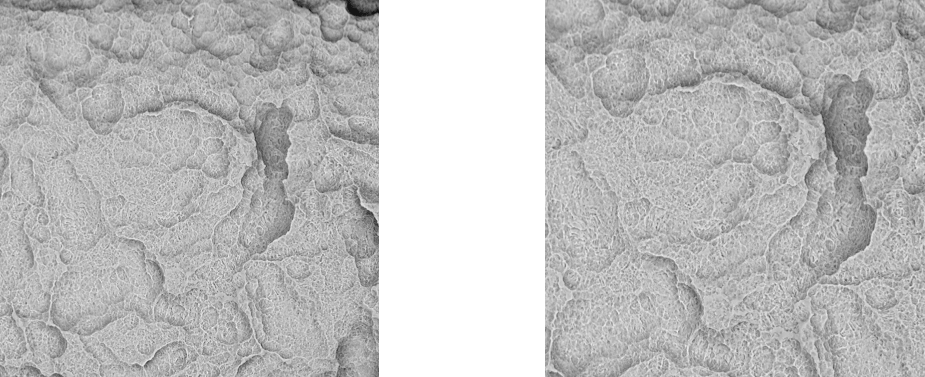
Surface-Topography - Material Contrast Images (Thread)
3.3 Surface-Topography - Material Contrast Images (Body)
Surface-Topography - Material Contrast Images (Body)
3.4 EDX Area Analysis
4 Synopsis
Name of Manufacturer:
Analyzed Product(s):
Title of Study:
Investigators:
Study centre:
Study carried out by:
Studied period:
Methodology:
Summary/Conclusions:
Alpha-Bio Tec Ltd.
SPI Spiral Implant LOT 14111986 Exp.Date:2019-10
Implant-Study 2014/2015
Quantitative and qualitative element-analysis of implant- surfaces by SEM and EDX
Dr. Dirk U. Duddeck
Interdisciplinary Outpatient Dep. For Oral Surgery and Implantology, Dep. for Craniomaxillofacial and Plastic Surgery, University of Cologne
dedeMED - Medical Materials Research Institute Berlin
September 2014 – May 2015
Phenom proX Scanning Electron Microscope, equipped with high-sensitivity backscattered electron detector (compositional & topographical modes)
EDX Analysis:
Detector type: Silicon Drift Detector (SDD) Thermoelectrically cooled (LN2 free)
Detector active Area: 25 mm2
X-ray window: Ultra-thin Silicon Nitride (Si3N4) window allowing detection of elements C to Am
Energy resolution Mn Kα ≤ 140 eV Max. Input count rate: 300,000 cps
The implant “SPI Spiral Implant” provided by Alpha-Bio Tec for this analysis showed no significant traces of inorganic or organic residues and high mechanical precision.
5 Coordinating Investigator(s) Signature(s)
STUDY AUTHOR (S):
STUDY TITLE:
Dr. Dirk U. Duddeck
Interdisciplinary Policlinic - Dep. for Oral Surgery and Implantology, Dep. for Craniomaxillofacial and Plastic Surgery, University of Cologne, Head: Prof. Dr. Dr. Joachim E. Zöller,
Address: Kerpener Str. 62, D 50937 Köln, Germany,
eMail: duddeck@dedemed.de
Implant-Study 2014/2015 Quantitative and qualitative element-analysis of implant-surfaces by SEM/EDX
I have read this report and confirm that to the best of my knowledge it accurately describes the conduct and results of the study.
DATE:
INVESTIGATOR:
May 18, 2015
Dr. Dirk U. Duddeck